Kann die Empfängerleistung die Kommunikationsreichweite vorausbestimmen?
Einführung
Im letzten Artikel „Empfängerspezifikationen verstehen“ haben wir uns die verschiedenen Parameter angesehen, die normalerweise im Datenblatt eines Funkempfängers zu finden sind. Wir können zwar den Einfluss eines Parameters auf das empfangene Signal messen, aber der nächste Schritt ist: Wie gut wird unser Kommunikationskanal funktionieren? Wenn der Benutzer nicht sicher einschätzen kann, ob das Funkmodul die gewünschten Nutzdaten empfangen kann, wird er sich nicht die Mühe machen, das Modul weiter zu untersuchen.
Warum der Fokus auf den Empfänger?
Wenn wir die Kommunikationseigenschaften nur in Bezug auf die Funkschaltkreise und -komponenten vorhersagen (ohne externe Faktoren wie Antennengewinn, Kabelverlust, Protokoll usw. zu berücksichtigen), dann ist der Empfänger ein guter Ausgangspunkt.
Die Aufgabe des Senders besteht darin, das Hochfrequenzsignal zu erzeugen und es an die Sendeantenne zu übertragen. Im Vergleich zu einem Empfänger ist dieser Vorgang recht einfach.
Da die Parameter des Senders durch die Normen festgelegt sind, können wir davon ausgehen, dass dieser Teil der Kommunikationsverbindung stets gleichbleibt, und uns auf den Empfänger konzentrieren. Die Konzeption des Empfängers können wir besser steuern.
Eine etwas bessere Empfängerleistung kann den Unterschied ausmachen
Inwieweit können wir unsere Kommunikation anhand der Spezifikationen des Empfängers vorhersagen?
Zunächst einmal: Was gilt als „erfolgreiche Kommunikation“? Und was ist der Unterschied zwischen der Übertragung von kontinuierlichen Signalen und einem Datenstrom?
Bei kontinuierlichen Signalen wie der Audioübertragung wird das Signal zunehmend schwächer, bis es vom Rauschen vollständig überlagert wird. Es gibt keine „Schwelle“, sondern nur einen ungefähren Pegel, bei dem das Signal nicht mehr „verständlich“ ist. Jedoch gibt es eine standardisierte Messung an solchen Empfängern zur Bestimmung des Eingangspegels, der noch „verständliche“ Signale liefern kann.
Weitere Einzelheiten finden Sie im Artikel „Was ist 12 dB SINAD?“.
Bei einem Datenstrom würde eine perfekte Kommunikationsverbindung immer genau das gleiche Ausgangssignal erzeugen wie das, was als Eingangssignal vorhanden war. Allerdings kann kein Funkgerät eine völlig fehlerfreie Verbindung herstellen. Es besteht immer eine gewisse Wahrscheinlichkeit, dass ein fehlerhaftes Paket empfangen wird, und diese Wahrscheinlichkeit steigt mit zunehmender Entfernung. Außerdem gibt es verschiedene äußere Einflüsse wie Störsignale von anderen Geräten. Bei industriellen Anwendungen, bei denen die Sicherheit von entscheidender Bedeutung sein kann, muss der Empfänger genau das liefern, was am Sender eingespeist wurde. Daher ist neben einem guten Empfänger in der Regel auch ein gutes Protokoll und ein System zur Erkennung/Korrektur von Fehlern erforderlich.
Weitere Einzelheiten finden Sie im Artikel „Voraussetzungen für eine transparente Schnittstelle“.
Verstehen der Benutzer-Anforderungen in Bezug auf den benötigten Empfängertyp.
Es kann schwierig sein, die Leistungsfähigkeit der Kommunikation, die dem Benutzer vorschwebt, mit dem exakt zu verwendenden Empfänger zu verknüpfen. Der Benutzer, der über umfangreiche Kenntnisse im Bereich Funktechnik verfügen kann, kann die Übertragungsstrecke zwar beschreiben, aber nur in allgemeiner Form. Es ist ein dritter Schritt erforderlich, um diese Anforderungen zu interpretieren und zu bestimmen, welche Aspekte des Empfängers die größte Berücksichtigung erfordern.
Welche Empfänger-
parameter sind wichtig?
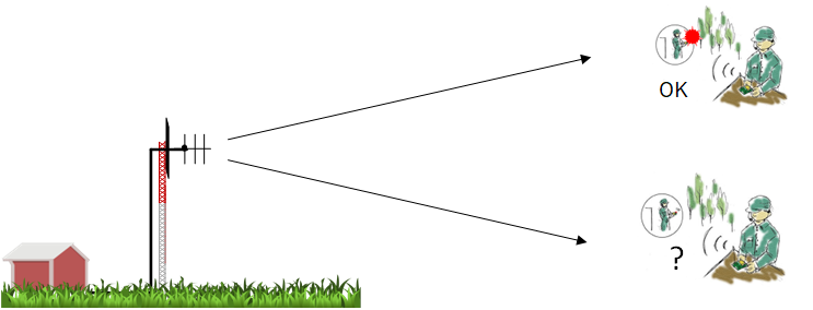
Übertragungsreichweite
Die Reichweite ist die Entfernung zwischen Sender und Empfänger, bei der die Voraussetzungen für eine erfolgreiche Übertragung erfüllt sind.
Um eine vorläufige Schätzung vorzunehmen, erstellen Ingenieure ein Link-Budget. Da die Streckendämpfung von der Entfernung abhängt, wird dies im Link-Budget berücksichtigt. Die Empfindlichkeit als einer der Empfangsparameter ist der niedrigste Signalpegel, der dem Empfänger präsentiert wird, bei dem das Signal vom Empfänger noch demoduliert werden kann. Wenn die Streckendämpfung zu groß ist, fällt der Signalpegel auf ein Niveau, das für die Demodulation zu schwach ist.
Weitere Einzelheiten finden Sie in den Artikeln „Link-Budget“ und „Ausbreitung von Funkwellen“.
Link-Budget
Wir können feststellen, dass eine Verbindungsmarge zur Berücksichtigung von Schwankungen erforderlich ist, um einen stabilen Empfang zu gewährleisten. Durch die Verbindungsmarge und die Kenntnis der Empfindlichkeit können wir einen nutzbaren Wertebereich ermitteln.
Rauschen
Das Link-Budget nimmt jedoch an, dieses Signal ist das Einzige, was wir empfangen. Leider gibt es bei jeder realen Funkverbindung auch Rauschen, was die Empfindlichkeit verringert. Ein realistisches Link-Budget, das auch das Rauschen berücksichtigt, bedeutet also, dass wir nicht einfach den Empfindlichkeitswert aus dem Datenblatt übernehmen können.
Mehrere Sender und das Near-Far-Problem
Leider kann eine höhere Empfängerempfindlichkeit auch dazu führen, dass der Empfänger Signale empfängt, die unerwünscht sind. Dies geschieht, wenn Sender benachbarte Kanäle verwenden. Eine höhere Empfindlichkeit würde zwar die Reichweite verbessern, aber auch bedeuten, dass diese anderen Sender räumlich getrennt werden müssten, um ihre Störwirkung zu verringern. Um dies zu vermeiden, muss neben der Empfindlichkeit auch die Kanalselektivität erhöht werden.
Near-Far-Problem
Anzahl der Kommunikationskanäle
Der Benutzer benötigt möglicherweise mehr als nur eine Kommunikationsverbindung, beispielsweise ein Kommunikationsnetzwerk. Dies würde Funkmodule erfordern, die in der Lage sind, auf einem eigenen Kanal zu kommunizieren. Die Annahme ist, dass wir mehrere Kommunikationsverbindungen herstellen können, von denen jede die gleiche Leistungsfähigkeit wie eine einzelne Verbindung hat.
Solange der Empfänger nur den gewünschten Kanal durchlässt, während alle anderen Signale draußen bleiben, gibt es kein Problem. Leider sind Filter im Empfänger nicht ideal, und starke Signale von anderen Kanälen und Bändern können ebenfalls eindringen. Diese stören das gewünschte Signal, wenn Nachbarkanalselektivität und Blocking des Empfängers schwach sind.
Mehrere Kanäle im selben Bereich
Eine Empfangsantenne erfasst viele Signale im selben Bereich und leitet diese an den Empfänger weiter.
In der Regel enthält ein Empfänger einen rauscharmen Verstärker in einer der ersten Stufen. Normalerweise ist ein Verstärker ein lineares Element, aber starke Signale im Bereich des Empfängers können ihn in den nichtlinearen Bereich bringen. Dadurch entstehen Intermodulationsprodukte, die die Anzahl der nutzbaren Kanäle begrenzen.
Weitere Einzelheiten siehe “Intermodulation 3. Ordnung / Kanalplan”
Datenrate
Für die Datenübertragung stellt sich der Benutzer eventuell eine bestimmte Datenrate vor.
Im Allgemeinen bestimmt die Datenrate die Bandbreite des HF-Signals, das übertragen werden soll. Dieses Signal muss in das Fenster des Empfängers „passen“ und wird als Kanalbandbreite bezeichnet. Bei einem Superheterodyn-Modul entspricht die Kanalbandbreite der Breite des ZF-Filters des Empfängers.
Je genauer die Kanalbandbreite mit dem übertragenen Signal übereinstimmt, desto besser. Wenn diese Bandbreite zu schmal ist, kann unser Signal nur schwer erfasst werden. Andererseits besteht bei einer zu breit ausgelegten Kanalbandbreite eine höhere Wahrscheinlichkeit, dass unerwünschtes Rauschen empfangen wird. Auch bandbreitenabhängiges internes Rauschen (thermisches Rauschen) senkt das Signal-Rausch-Verhältnis weiter.
Weitere Informationen finden Sie im Artikel „Filter und die Entwicklung eines Funksystems“ unter Punkt 5.3 „Isolierung der Zwischenfrequenz“.
Fazit
Da der Empfänger viel mehr Stufen hat als ein Sender, ist er komplexer und hat daher den größten Einfluss.
In diesem Artikel haben wir versucht, unsere Prognosen allein auf die Empfängerparameter zu stützen. Um die Kommunikationsverbindung richtig bewerten zu können, muss sie jedoch in der jeweiligen Umgebung mit dem tatsächlichen Modul getestet werden. Aufgrund von Umgebungsfaktoren wie Hindernissen, der Platzierung der Antenne, der Fresnel-Zone usw. kann es vorkommen, dass die Reichweite geringer ist als optimal.
Circuit Design bietet zum Beispiel ein Evaluierungsprogramm zum Testen der Modems der MU-Serie an. Es ist für die Verwendung auf einem Laptop mit einer Schnittstellenkarte für die Kommunikation mit dem Funkmodem konzipiert und ermöglicht Ihnen die Durchführung realer Kommunikationstests im Feld.